Module 2 · Chapter 1 · Concept + Lab
Coordinate Reference Systems
Choose, inspect, assign and transform coordinate reference systems without confusing metadata repair with reprojection.
Open this lesson in the Academy workspace1. Connect coordinates to the curved Earth
Learning outcome
By the end of this lesson, you will be able to inspect a coordinate reference system, distinguish geographic and projected coordinates, choose an analysis CRS for a stated purpose, and transform vector data without confusing CRS assignment with coordinate transformation. You will add a before-and-after CRS audit to the UAV and Satellite Analysis Pipeline.
Prerequisites: Complete Lesson 2.1. You should be able to distinguish tabular, vector and raster representations and explain why coordinates without a CRS are ambiguous. Allow 90–120 minutes.
Why this matters
Distance, area, direction and overlay are not properties of coordinate numbers alone. They depend on the reference system that gives those numbers meaning. A five-unit distance could mean five degrees, five metres or something else. Two layers can depict the same coast and still fail to overlap because their coordinate values use different reference systems.
CRS errors are unusually dangerous because software often continues running. A layer may appear in the wrong country, an area may be calculated in square degrees, or a dataset may align only because incorrect metadata were assigned to it. Professional work therefore records CRS evidence before processing and verifies the result after transformation.
Core spatial question: Which reference system makes the intended measurement or overlay meaningful for this study area?
Scientific context
The published Baltic plant-traits table still has no plot coordinates. Do not invent them. In this lesson you will use one clearly labelled instructional control point near the Estonian coast to learn CRS operations. It is not a published sampling location.
The research group has two instructional spatial representations:
- a control point recorded as longitude
24.75and latitude59.45in WGS 84; - a management-zone layer recorded in the Estonian Coordinate System of 1997, EPSG:3301.
Your task is to place both in one justified analysis CRS while preserving the same Earth locations.
Learner action
Add ## Lesson 2.2 — Coordinate reference systems to the Module 2 notebook. Before writing code, record the analysis you intend to perform: compare a point with a management zone and later measure distances in metres. This purpose will guide the CRS decision.
2. A reference frame connects coordinates to Earth
Earth is irregular and curved. A coordinate reference system uses a mathematical Earth model and a set of conventions to describe positions.
At an introductory level, separate four components:
- Datum or reference frame: the realised system that connects coordinates to Earth through defined reference points, observations, models and an ellipsoid. Modern reference frames can also include a reference epoch because Earth changes through time.
- Coordinate system: the axes, axis directions and units used to express a position.
- Projection: a mathematical method that represents the curved surface on a plane.
- Area of use: the region where the CRS is intended to provide controlled distortion.
A datum is not merely “ellipsoid plus origin,” and it is not a unit label. Coordinates expressed in different reference frames can refer to different Earth locations even when their numbers look similar. Modern transformations use defined coordinate operations and may depend on grids, epochs and installed resources. Record package versions, operation details and warnings because the best available transformation can depend on the environment.
3. Geographic and projected CRSs answer different needs
A geographic CRS describes location with angular coordinates on the reference ellipsoid. Longitude measures angle east or west; latitude measures angle north or south. The units are usually degrees.
Degrees are not constant ground distances. One degree of latitude covers a broadly similar north–south distance across the globe, but the east–west distance represented by one degree of longitude decreases toward the poles. This makes ordinary Euclidean distance, area and buffering in degrees unsuitable for a metre-based field question.
A projected CRS converts part of the curved surface to planar coordinates such as easting and northing, often measured in metres. Projection always introduces distortion. A suitable projected CRS controls the distortion that matters for the study purpose and geographic extent; it does not eliminate distortion everywhere.
For an Estonia-focused analysis, EPSG:3301 provides a nationally used projected CRS with metre units and a relevant area of use. It is a defensible candidate for local overlay and distance work, provided the full study extent and accuracy requirements are compatible. A global web map projection is not automatically the right analytical CRS merely because a basemap uses it.
Go deeper — horizontal, vertical, geodesic and projected questions
A horizontal CRS describes position across Earth. A vertical CRS or stated vertical reference explains what a height is measured relative to. Ellipsoidal height from a satellite-positioning workflow and orthometric height related to a gravity-based surface are not interchangeable.
This matters for UAV surface products:
- a DSM represents the elevation of visible surfaces such as vegetation, buildings and ground
- a DTM estimates the terrain surface after an explicit ground-classification and interpolation process
- subtracting DTM from DSM can support a height-above-terrain product only when grids, units and horizontal and vertical references are compatible
Do not call an elevation field “metres above sea level” unless its vertical reference and processing support that statement.
Distance also has two legitimate approaches. A projected distance uses planar coordinates in a CRS chosen for the area and task. A geodesic distance follows the reference ellipsoid and is useful when working directly with longitude and latitude or over extents where one planar choice is unsuitable. PyProj exposes forward and inverse geodesic computations through Geod:
from pyproj import Geod

geod = Geod(ellps="WGS84")
azimuth, back_azimuth, distance_m = geod.inv(
    24.75, 59.45, 24.76, 59.46
)
print(round(distance_m, 1), "m")
Before running, predict whether this number should be interpreted as a planar map distance or an ellipsoidal geodesic. The answer is geodesic: Geod.inv() solves the inverse problem between two longitude–latitude positions on the specified ellipsoid. It does not validate the coordinates or their positional accuracy. For a local workflow, compare it with distance in a justified projected CRS and explain any difference rather than assuming the methods are identical.
4. EPSG identifiers are references, not explanations
An EPSG identifier is a compact authority code for a coordinate reference system or coordinate operation in the EPSG Dataset. EPSG:4326 identifies WGS 84 geographic coordinates. EPSG:3301 identifies the Estonian Coordinate System of 1997.
The code is useful because software can retrieve a structured definition. It is not a substitute for inspecting that definition. For every CRS used in analysis, check:
- name and type;
- datum or reference frame;
- axes and units;
- area of use;
- projection method for a projected CRS;
- transformation operation and warnings when moving from another CRS.
Do not infer quality from the number. A valid EPSG code can still be inappropriate for the study area or analysis purpose.
5. Assigning and transforming are different operations
This distinction is one of the most important in practical GIS:
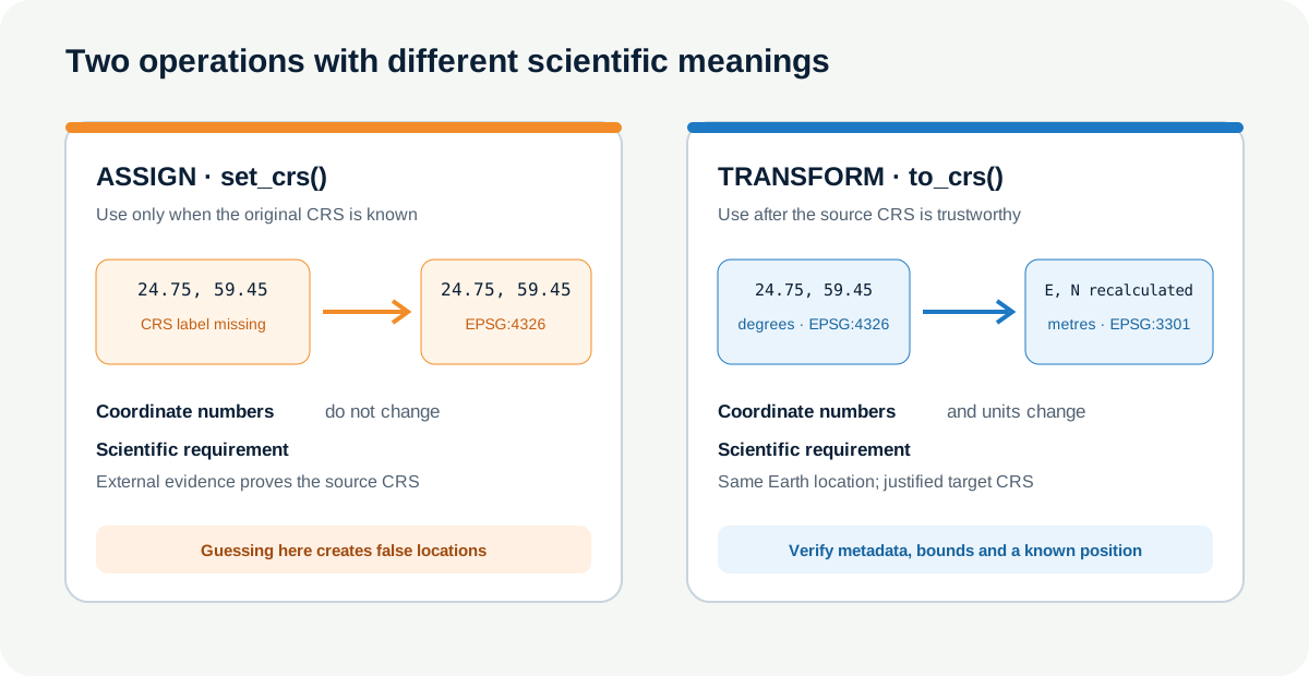
set_crs()assigns metadata to existing coordinate numbers. The coordinates do not change. Use it only when reliable external evidence identifies the original CRS but the file is missing that label.to_crs()calculates new coordinate numbers representing the same Earth locations in another CRS. It requires a correct source CRS.
If longitude–latitude values are incorrectly labelled EPSG:3301 with set_crs(), the software interprets 24.75 and 59.45 as metre coordinates. The point has not been transformed; it has been misdescribed. A later transformation then produces a confidently wrong result.
6. Worked example — transform one verified control point
Before running, predict which properties will change and which must remain conceptually unchanged:
- coordinate numbers;
- units;
- CRS name;
- point identifier;
- Earth location.
import geopandas as gpd

control_wgs84 = gpd.GeoDataFrame(
    {"record": ["instructional_control"]},
    geometry=gpd.points_from_xy([24.75], [59.45]),
    crs="EPSG:4326",
)
control_lest97 = control_wgs84.to_crs("EPSG:3301")

print(control_wgs84.crs, control_wgs84.geometry.iloc[0])
print(control_lest97.crs, control_lest97.geometry.iloc[0])
print(control_lest97.crs.axis_info[0].unit_name)
The first output uses angular longitude–latitude values. The transformed point uses metre-based projected values. Your exact textual CRS display can vary by library version, but the target CRS should be EPSG:3301 and the reported axis unit should be metre.
Code walkthrough
import geopandas as gpdmakes GeoPandas available using its conventional short name.GeoDataFramecreates a spatial table with one instructional record.- The attribute dictionary preserves the record identifier separately from geometry.
points_from_xyinterprets x as longitude and y as latitude for these values.crs="EPSG:4326"records the known source CRS at construction time; it does not repair unknown data.to_crs("EPSG:3301")creates a transformed GeoDataFrame. The source object remains available for audit.- The first print instruction exposes the source CRS and source coordinate pair.
- The second exposes the target CRS and recalculated projected coordinate pair.
axis_info[0].unit_nameinspects the target unit rather than assuming it from the coordinate magnitude.
The point identifier remains unchanged because it is an attribute. The coordinate values and units change. The intended Earth location must remain the same.
7. Build a before-and-after CRS audit
Do not rely on a single print(gdf.crs). Record a compact audit for each layer:
| Check | Before transformation | After transformation |
|---|---|---|
| source file or object | stable path or name | derivative path or name |
| CRS identifier and name | verified source | selected target |
| CRS type | geographic/projected | geographic/projected |
| axis units | degrees/metres | degrees/metres |
| feature count | expected count | must be preserved |
| geometry type | expected type | must be preserved |
| bounds | source coordinate range | target coordinate range |
| sample coordinate | one traceable feature | transformed counterpart |
| independent check | known landmark or authoritative layer | same Earth position |
Bounds are a fast plausibility check, not proof. A layer can have plausible national-scale bounds and still be shifted by hundreds of metres. When accuracy matters, compare known control points or an authoritative reference whose own accuracy and date are documented.
8. Axis order and software conventions
Coordinates are often described casually as “lat/long,” while geometry software usually stores planar tuples as (x, y). For longitude–latitude data, x normally means longitude and y means latitude in common GIS workflows and in RFC 7946 GeoJSON positions.
Formal CRS definitions can specify axis order differently. Libraries have developed compatibility conventions to manage this history. Avoid solving the problem by memory alone:
- inspect the CRS axes;
- inspect a known coordinate;
- use explicit longitude and latitude variable names;
- when using
pyproj.Transformerdirectly, consideralways_xy=Truewhere x/y order is required; - verify the output against a known location.
An axis-order mistake often places a feature far from the study region. Near symmetric coordinate values or broad map extents can make it harder to notice.
9. Common mistakes and recovery
Using set_crs() to make layers overlap
Why it happens: assigning a label is fast and the map changes immediately. Recognition: coordinate numbers remain unchanged although the claimed reference system changes. Fix: recover the verified original CRS, assign it only if metadata were genuinely missing, then use to_crs().
Measuring in degrees
Why it happens: the layer is already displayed correctly in longitude and latitude. Recognition: distance or buffer units are degrees, or results vary strongly with latitude. Fix: select a projected CRS appropriate to the study area and measurement purpose.
Choosing a projection because a basemap uses it
Why it happens: visual alignment is mistaken for analytical suitability. Recognition: the justification mentions the web display but not distortion, units or area of use. Fix: separate the display CRS from the analysis CRS.
Trusting automatic reprojection without inspecting the source
Why it happens: desktop GIS can reproject layers on the fly. Recognition: layers overlap on screen but their stored CRS and bounds were never recorded. Fix: audit stored metadata and create an explicit transformed derivative.
Overwriting the source layer
Why it happens: transformation feels like a correction. Recognition: no original coordinates remain for comparison. Fix: keep raw inputs immutable and write a clearly named derivative with processing metadata.
10. Guided practice — bring two datasets into one CRS
Create two instructional GeoDataFrames in your notebook:
field_reference_wgs84: two verified training control points in EPSG:4326. Use clearly labelled fictional IDs and state that they are not published field plots.management_zone_lest97: one simple training polygon in EPSG:3301 enclosing the transformed control-point area.
Then complete this protocol:
- Print CRS name, type, axis units, bounds, geometry type and row count for both datasets.
- Explain why the layers should not be compared numerically in their current coordinate representations.
- Transform the points to EPSG:3301 with
to_crs(). - Repeat the audit and compare counts and geometry types.
- Plot the transformed points with the polygon only as a visual QA step.
- Verify one transformed position with an independent trusted map or coordinate service and record the source and access date.
- Write the derivative to a new filename; do not overwrite the input object or file.
Required QA evidence
Your notebook must show CRS, units, bounds and one sample coordinate before and after transformation. It must state why EPSG:3301 is suitable for this Estonia-focused training task and that a different region or global analysis could require a different choice.
11. Independent challenge — diagnose a CRS handover failure
You receive a point layer with coordinates near (542000, 6584000) but crs is None. A colleague suggests set_crs("EPSG:3301") because the values look plausible.
Write a response protocol before touching the data:
- identify the evidence you would request from the producer;
- list at least two plausible failure modes, including axis or unit problems;
- explain when
set_crs("EPSG:3301")would become defensible; - explain why testing several CRSs visually is insufficient;
- define the before-and-after evidence you would preserve;
- state when you would reject the asset rather than repair it.
If you have a genuinely verified CRS definition, create a separate copy, assign the source CRS, transform it to a justified target, and label every step as an instructional repair. Never present the coordinate pair as a published Baltic sampling position.
Scientific interpretation
A successful transformation establishes that software applied a defined coordinate operation. It does not prove the source coordinates were correctly measured, that the source CRS label was true, or that positional accuracy is sufficient for matching a one-square-metre quadrat to fine UAV imagery. Those claims require provenance, survey information and independent spatial validation.
12. Reflection, submission and portfolio artifact
Answer in your private notes:
- What stays fixed on Earth when coordinates are transformed?
- Under exactly what evidence is
set_crs()appropriate? - Why can no flat projection preserve area, distance, shape and direction perfectly everywhere?
- Which property of EPSG:3301 makes it useful for this task?
- What accuracy evidence would you need before extracting a 5 cm UAV pixel at a field point?
Submission
- Notebook: the continuing pipeline notebook with the worked example, two-layer guided practice and CRS failure protocol.
- Screenshot: before-and-after audit showing CRS, units, bounds and sample coordinates.
- Written answer: 180–240 words explaining the difference between assigning and transforming a CRS, why the target CRS fits the task, and what the transformation cannot validate.
Portfolio artifact
Artifact 2.2 — CRS transformation audit
This artifact demonstrates that you can make spatial reference decisions transparently and preserve evidence before and after transformation. Add the audit function or table to the reusable input-validation stage of your UAV and Satellite Analysis Pipeline.
Keep the reviewed checkpoint in the continuing notebook and export it as crs_transformation_audit.ipynb for submission.