Module 2 · Chapter 4 · Concept + Workflow Lab
Structure from Motion and Photogrammetric Reconstruction
Trace overlapping perspective images through a software-independent three-dimensional reconstruction workflow. Practise with Structure from Motion, Bundle.
Open this lesson in the Academy workspace1. Understand the model behind the products
Learning outcome
By the end of this lesson, you will be able to trace overlapping images through feature detection, matching, tie points, camera pose estimation, bundle adjustment, sparse and dense reconstruction, surface modelling, orthorectification and mosaicking; and identify where blur, texture, motion, illumination and weak geometry enter the result.
- Lesson type: Concept + workflow lab
- Estimated time: 110–130 minutes
- Prerequisites: Lessons 2.19–2.21. You should distinguish image overlap, control and check points, and relative versus absolute accuracy.
Why this matters
Photogrammetry software can turn hundreds of photographs into a polished map with a few commands. A remote-sensing scientist must understand what those commands estimate. Otherwise, an internal diagnostic becomes “proof,” a failed area disappears behind a mosaic seam, or a reconstructed vegetation surface is interpreted as direct height.
The goal is software-independent reasoning. Pix4D, Agisoft Metashape and OpenDroneMap expose different options and terminology, but each implements variants of a shared image-geometry chain.
Scientific context
The synthetic processing report contains twelve images, eleven aligned images, thousands of keypoints and tie points, 0.42-pixel reprojection error, a 2.8% focal-length change and a weak south-east block edge. These values are not a pass/fail checklist by themselves. You will decide what each one can diagnose and what evidence is still missing.
Mental model
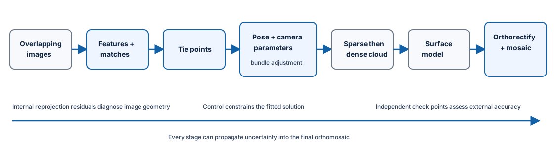
Learner action
Create 05_photogrammetry_concepts.ipynb. Add one Markdown table with columns stage, input, estimated output, assumption, diagnostic and downstream consequence.
2. Images are perspective projections
A raw camera image is a perspective view. The position of a ground feature in the frame depends on:
- the camera’s three-dimensional position and orientation;
- internal camera geometry;
- feature position and elevation;
- lens distortion;
- shutter and object motion.
Tall objects lean away from the perspective centre in an uncorrected image. The same feature appears at different image coordinates from different viewpoints. Photogrammetry uses those differences—parallax—to infer three-dimensional geometry.
An image is therefore not corrected by assigning a CRS. Reprojection of a 2-D raster changes coordinate representation; photogrammetric orthorectification models perspective with camera and surface geometry.
3. Feature detection finds distinctive image structures
Feature detectors identify repeatable local patterns such as corners or textured arrangements. They do not understand ecological objects. A strong feature may be a stone edge, soil pattern or leaf intersection.
Good features should be detectable across changes in viewpoint, scale and illumination. Homogeneous surfaces provide few. Repetitive patterns can produce ambiguous matches. Water changes appearance and lacks stable texture. Moving grasses do not occupy the same geometry across exposures.
The number of detected features is not a universal quality score. Distribution matters. Ten thousand features along one road do not constrain a uniform meadow edge.
Interpretation task
For water, short uniform grass, mixed flowering vegetation and a building roof, predict feature abundance, stability and potential matching ambiguity. Separate texture from scientific importance.
4. Feature matching proposes correspondence
Matching compares feature descriptions across image pairs. Mission geometry and geotags may restrict candidate pairs. Algorithms reject inconsistent matches using geometric models, but false and missed correspondences remain possible.
Overlap creates the opportunity for matching. It does not guarantee correspondence. Blur removes detail. Shadows alter appearance. Repetitive vegetation can match to the wrong patch. Very large viewpoint or illumination differences reduce similarity.
QA should examine:
- matched image network and disconnected components;
- match count and distribution per pair;
- spatial gaps within images;
- angles and baselines between observations;
- rejected matches and reasons;
- weak areas in the final block.
5. Tie points link multiple images
A tie point represents observations believed to correspond to one scene point across two or more images. Its image coordinates connect camera poses and 3-D geometry.
Tie points are not surveyed ground control. Their object coordinates are estimated within the reconstruction. More tie points can improve redundancy, but poorly distributed or erroneous points can bias geometry.
A sparse point cloud visualises reconstructed tie points. Sparse describes its role and density relative to dense reconstruction, not low scientific value. It is useful for diagnosing block shape, gaps, camera positions and large anomalies.
6. Camera pose and internal calibration
For each image, the reconstruction estimates external orientation:
- camera position;
- rotation about three axes.
It can also estimate internal camera parameters such as:
- focal length;
- principal point;
- radial and tangential distortion.
Self-calibration uses image geometry to refine these parameters. Strong calibration needs appropriate view geometry and parameter constraints. A mostly flat scene with similar nadir views can correlate camera parameters with block deformation. Cross-grid or oblique views may strengthen geometry in some missions, but no geometry removes the need for validation.
Compare estimated parameters with prior calibration and physical plausibility. The synthetic report’s 2.8% focal-length change is a review signal—not automatic failure. Investigate model, image geometry and parameter stability.
7. Bundle adjustment refines the connected model
Bundle adjustment jointly refines:
- camera poses;
- selected internal camera parameters;
- 3-D tie-point positions;
- control constraints and weights.
The objective reduces differences between observed image coordinates and projections predicted by the current model. These differences are reprojection residuals.
Bundle adjustment is not image reprojection into a map CRS. It is a geometric optimisation connecting cameras and points. The output remains conditional on observations, weights, model and geometry.
Worked example — classify processing evidence
Predict before running
Which report fields diagnose internal reconstruction, and which independently validate external position?
import json

with open("data/raw/photogrammetry_report.json") as file:
    report = json.load(file)

internal = {
    "aligned_fraction": report["imagesAligned"] / report["imagesTotal"],
    "reprojection_px": report["reprojectionErrorPixels"],
    "focal_change_pct": report["cameraFocalLengthChangePct"],
}

for metric, value in internal.items():
    print(metric, value)
print("independent position: check-point residuals required")
Code walkthrough
- JSON preserves a small software-neutral report.
- Aligned fraction reveals one image did not join the block.
- Reprojection error is expressed in image pixels.
- Focal-length change compares an estimated internal parameter with its starting value.
- These are all internal reconstruction diagnostics.
- None measures independent ground-coordinate error.
- The last line explicitly requests withheld check-point evidence.
- A useful audit connects the weak region to a spatial residual map.
8. Reprojection error is useful but limited
Low reprojection error means the fitted image observations agree well with the fitted camera-and-point model under the reported statistic. It can help find poor matches, badly marked control or model instability.
It does not by itself prove:
- correct absolute position;
- correct vertical datum;
- absence of systematic block deformation;
- accurate dense surface;
- radiometric quality;
- temporal compatibility;
- ecological validity.
Training residuals can become small in a biased or over-flexible model. Report distribution, image and point patterns, units, statistic definition and filtering—not only a global mean.
9. Dense reconstruction estimates more surface points
After sparse geometry is established, dense matching estimates depth for many more image locations. The resulting dense cloud can support surface models and orthorectification.
Dense reconstruction can fail where:
- texture is weak or repetitive;
- view geometry is poor;
- water reflects or changes;
- vegetation moves;
- areas are occluded;
- shadows and exposure differ;
- images are blurred;
- filters smooth or remove real detail.
Point density is not uniform accuracy. Dense points may be interpolated or confidence-filtered. Record depth quality, filtering, gaps and input image contributions.
Photogrammetric points represent visible image surfaces. LiDAR points arise from active ranging and may contain return structure. Do not transfer LiDAR classification assumptions to image-derived clouds.
10. Surface, orthorectification and mosaic
A surface model turns discrete points into a gridded or mesh representation. Orthorectification projects image content through camera and surface geometry to a map grid, reducing perspective displacement. The chosen surface matters: an incorrect height can displace image features horizontally.
An orthomosaic selects and blends contributions from multiple orthorectified images. Seamline placement, colour balancing and resampling influence pixels. The mosaic is a spatial compilation across viewpoints and times, not a single exposure.
The processing chain should retain:
- source image identifiers and times;
- camera and calibration model;
- tie-point and adjustment diagnostics;
- control/check roles;
- dense and surface settings;
- orthorectification surface;
- mosaic blending and resampling;
- software and version;
- output CRS, grid, mask and provenance.
11. Failure modes as causal chains
Moving vegetation
Wind changes leaf and stem positions. Matches become inconsistent; dense reconstruction becomes noisy; DSM texture and mosaic ghosting follow. Higher overlap can add more inconsistent observations rather than solve motion.
Water
Specular reflection and movement make appearance view-dependent. Tie points may be absent or false. Interpolated surfaces can bridge water with invented geometry.
Shadows and changing illumination
Features look different across views; matches can weaken. Mosaic blending can hide the acquisition transition while spectral values remain inconsistent.
Weak edge geometry
Features near the boundary appear in fewer images and directions. Camera and surface estimates become less constrained, so errors can increase even when central diagnostics are strong.
Blur
Fine structures disappear or move during exposure. Feature and dense matches decline. No reconstruction setting restores lost image information.
12. Common mistakes and recovery
Treating software buttons as theory
Why: menus are visible. Detect: workflow cannot be explained outside one package. Recover: map every operation to inputs, estimate, assumption and output.
High tie-point count means good reconstruction
Why: large numbers appear persuasive. Detect: distribution and geometry are absent. Recover: inspect match network, spatial coverage and residual patterns.
Low reprojection error proves map accuracy
Why: it contains “error.” Detect: check-point evidence is missing. Recover: label it internal and evaluate external residuals separately.
Dense cloud equals measured surface truth
Why: points look detailed. Detect: confidence, gaps and filtering are absent. Recover: retain uncertainty and compare with independent surface evidence.
Retrying settings until the map looks good
Why: visual success is immediate. Detect: no predefined QA or comparison record. Recover: preserve versions, hypotheses and objective validation.
13. Guided practice — audit the reconstruction report
- Inventory every field in
photogrammetry_report.json. - Assign it to acquisition, internal reconstruction, external accuracy or missing evidence.
- Calculate aligned-image fraction.
- Explain what 0.42-pixel reprojection error means and does not mean.
- Flag 2.8% focal-length change for calibration review.
- Locate the unaligned-image risk in
image_metadata.csvand inspect blur/illumination candidates. - Connect the weak south-east region to check-point residuals.
- List expected failure behaviour over water and moving vegetation.
- Identify required dense-cloud, surface and mosaic settings absent from the report.
- Produce a table of
strong indicator,warning,missing evidence,consequenceandaction. - Write an acceptance decision for internal reconstruction and a separate decision for absolute georeferencing.
- Keep software-specific terms in a crosswalk, not the main explanation.
QGIS visual QA companion
Plot camera centres if available in a real handover, tie-point density summaries, control/check vectors and weak regions. QGIS reveals spatial distribution; the processing package and Python report supply quantitative reconstruction evidence.
QA checklist
- Perspective geometry is distinguished from raster reprojection.
- Feature, match and tie-point distribution are reviewed.
- Camera pose and internal parameters are separated.
- Bundle adjustment is explained as joint refinement.
- Reprojection error is labelled internal.
- Dense reconstruction gaps and filtering are recorded.
- Surface and mosaic decisions are traceable.
- External accuracy and radiometry remain separate QA gates.
14. Independent challenge — diagnose three failed scenes
For each scene below, trace the likely effect through features, matches, bundle adjustment, dense cloud, surface and mosaic:
- a wind-exposed reed bed with repeated vertical texture;
- a calm water channel with sun glint;
- a sharp central block with weak overlap at the southern edge.
Propose acquisition prevention, processing diagnosis, validation evidence and final product status. Do not claim that increasing one software-quality setting repairs missing observations.
Scientific interpretation
Structure from Motion creates a coherent three-dimensional model from repeated perspective observations. Its outputs are estimates shaped by image information, geometry, calibration, control, optimisation, filtering and interpolation. Understanding the chain lets you locate uncertainty rather than treating an orthomosaic as a neutral photograph.
15. Reflection, submission and portfolio artifact
Answer in your private notes:
- What do feature matching and tie points contribute?
- What does bundle adjustment jointly refine?
- What does reprojection error mean and not mean?
- How do sparse and dense clouds differ?
- Why are water and moving vegetation difficult for SfM?
Submission
- Notebook:
05_photogrammetry_concepts.ipynbwith report classification. - Table: stage–assumption–diagnostic audit.
- Diagram: one causal failure chain.
- Written answer: 300–380 words evaluating the synthetic reconstruction evidence.
Portfolio artifact
Artifact 2.22 — Photogrammetric reconstruction audit
Add the workflow table, failure diagnosis and evidence gaps to the Professional UAV Product Audit and Processing Report.