Module 2 · Chapter 4 · Scientific Measurement Lab
Sensors, Illumination and Radiometric Quality
Trace digital values through exposure, illumination and calibration evidence before calling them comparable reflectance.
Open this lesson in the Academy workspace1. A pixel value needs a measurement history
Learning outcome
By the end of this lesson, you will be able to distinguish digital number, radiance and reflectance conceptually; diagnose exposure, saturation, illumination and vignetting problems; explain the roles and limitations of reference panels and irradiance sensors; and design a radiometric QA protocol for UAV imagery.
- Lesson type: Scientific measurement lab
- Estimated time: 100–120 minutes
- Prerequisites: Lesson 2.18 and basic array summaries. No radiative-transfer mathematics is required.
Why this matters
Vegetation indices compare spectral bands. Change detection compares flights. Both assume that pixel values represent comparable measurement quantities. A bright pixel may indicate the surface, illumination, exposure, sensor response, directional geometry or processing. If those influences are not separated, ecological interpretation begins with an untested assumption.
Scientific context
The synthetic mission began under stable light, then thin cloud affected flight line L03. Exposure changed from 0.0016 s to 0.0022 s, irradiance declined and one image shows elevated saturation. The training pack also contains a west–east brightness gradient and a Red Edge band whose numeric scale is deliberately ambiguous.
The goal is not to “correct” every issue automatically. It is to determine which products are comparable, which require documented processing and which must remain under review.
Mental model
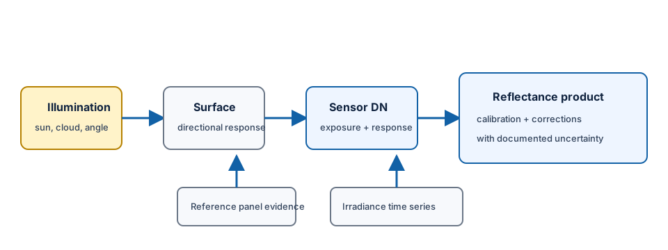
illumination × surface directional response → radiance at sensor
sensor response + exposure + electronics → digital number
calibration and corrections + metadata → estimated reflectance product
Learner action
Create 03_radiometric_quality.ipynb. Write one sentence defining the quantity needed for your analysis. If you need reflectance comparability, do not label digital numbers “reflectance” before verifying the product definition.
2. Digital number is a stored sensor response
A digital number, or DN, is a numeric value produced through detector response, amplification, exposure, analogue-to-digital conversion and sometimes in-camera processing. It can be useful, but its units and comparability depend on the product.
Two images of an unchanged target can have different DNs because:
- exposure time or gain changed;
- incident irradiance changed;
- sensor temperature or black level changed;
- the target was viewed from another direction;
- vignetting changed response across the frame;
- a rendered RGB pipeline applied white balance, tone curves or compression.
A filename such as NIR.tif identifies intended band content, not measurement scale. Read tags, sidecar metadata and processing documentation.
3. Radiance and reflectance answer different questions
Radiance describes radiant energy reaching the sensor per defined area, direction and spectral interval. It depends on the surface and illumination-view geometry.
Reflectance describes surface response relative to incident illumination under a defined reflectance concept and processing model. It is useful for comparison, but a retrieved UAV reflectance estimate remains conditional on calibration, irradiance, atmosphere, geometry and sensor behaviour.
This lesson does not derive radiative transfer. The practical discipline is to record:
- what the stored values claim to represent;
- units or scale factor;
- calibration inputs and software;
- whether exposure and gain were normalised;
- whether irradiance varied;
- what directional and atmospheric effects remain;
- valid numeric range according to the product definition.
Do not universally assume reflectance lies in stored values 0–1. Some files store scaled integers such as an intended 0–10,000 range. Others use floats or proprietary transforms. Only authoritative metadata can supply the scale.
4. Illumination is spatial and temporal
During a mission, sun angle changes and clouds move. Shadows move across tall vegetation. Water and glossy leaves can produce directional highlights. The opposition or “hotspot” direction can brighten vegetation when illumination and view directions align. These are aspects of bidirectional reflectance distribution: surfaces can respond differently with illumination and viewing angle.
The orthomosaic blends source images acquired at different times and view angles. A seam can therefore be radiometric even when geometry is good. An algorithm may hide brightness transitions visually without restoring a physically consistent measurement.
Track image time and irradiance alongside mosaic location. A spatial gradient aligned with flight order rather than environmental structure is a warning.
Interpretation task
The west half of a meadow was imaged in direct sun and the east half under thin cloud. A smooth colour-balancing tool removes the visible boundary. List what visual appearance improved and what measurement evidence is still needed before comparing reflectance.
5. Reference panels provide known-target evidence
A calibrated reflectance panel is a target with documented directional-spectral properties used under a sensor-specific protocol. Panel images can connect camera response to a reference before or after a flight.
Useful panel practice includes:
- using a suitable, documented panel;
- keeping it clean and undamaged;
- avoiding operator shadows and specular angles;
- filling sufficient pixels without clipping;
- recording time, exposure and environmental conditions;
- following the sensor and processing protocol;
- capturing before and after when required.
A panel does not guarantee perfect reflectance. Illumination can change between panel and scene. Automatic exposure can differ. The panel may be saturated, shaded, dirty or viewed at a problematic angle. Vignetting and inter-band registration can remain. Treat it as calibration evidence, not a certificate.
6. Irradiance sensors track changing incident light
A downwelling-light or sunlight sensor records incoming illumination during acquisition. Some systems use measurements to compensate image response over time. Its usefulness depends on calibration, orientation, shading, timing synchronisation and processing.
Record:
- what quantity the sensor reports;
- time basis and synchronisation;
- spectral correspondence with image bands;
- orientation or attitude correction;
- missing or implausible values;
- how the processing used the record.
An irradiance record can reveal the L03 cloud transition, but it does not automatically correct view-dependent canopy response or shadows within the scene.
7. Exposure, saturation and underexposure
Exposure time, aperture where adjustable, gain/ISO and illumination determine recorded signal. Automatic exposure can keep images visually useful while changing the DN-to-radiance relationship. A quantitative mission may require controlled settings or a documented metadata-aware correction.
Saturation occurs when the detector or stored representation reaches its maximum. The true signal above that limit is lost. No later scaling can reconstruct it. Review saturation by band; near-infrared vegetation can saturate even if RGB looks acceptable.
Underexposure produces low signal relative to noise and quantisation. Brightening the image does not recover lost signal-to-noise ratio.
The 6.4% saturation fraction for IMG_0010 is not automatically a mission failure. Locate affected bands and surfaces, compare the criterion chosen before analysis and determine whether the intended plots are affected.
Worked example — flag image-level conditions
Predict before running
Which images will receive review, and is the rule evidence of reflectance calibration?
import csv

with open("data/raw/image_metadata.csv", newline="") as file:
    rows = list(csv.DictReader(file))

for row in rows:
    saturated = float(row["saturation_fraction"]) > 0.02
    blurred = float(row["blur_score_px"]) > 1.0
    changed_exposure = float(row["exposure_s"]) != 0.0016
    row["status"] = "review" if any(
        [saturated, blurred, changed_exposure]
    ) else "pass"
    print(row["image_id"], row["status"])
Code walkthrough
- The standard library reads the transparent CSV fixture.
- Numeric fields arrive as strings and are converted to floats.
- Each threshold represents a predeclared training rule, not a universal standard.
- Saturation, blur and exposure change are separate conditions.
any()flags an image when at least one condition needs review.- The output identifies candidates for spatial and band-specific diagnosis.
- A pass does not prove calibrated reflectance; it only passes these three checks.
- A review does not mean delete; it directs the next investigation.
QA check
Add columns for evidence, scientific_consequence and action. Do not use status alone. “Review” must tell another analyst what to inspect.
8. Vignetting and field-dependent response
Vignetting is reduced brightness toward image edges due to optical and geometric effects. Sensor-specific calibration can model it, but coefficients, band and processing version matter.
In an orthomosaic, vignetting can create repeated brightness patterns related to image footprints or seamline choices. Diagnose it by examining calibrated source images, normalised radial profiles and contribution maps. A mosaic-wide ecological gradient that repeats with flight geometry is suspicious.
Do not fit an arbitrary surface to remove every gradient. Real moisture or vegetation gradients can have similar appearance. Corrections need physical or calibration evidence and must preserve raw inputs.
9. Multispectral co-registration is radiometric QA too
Separate bands may be acquired through distinct lenses, detectors or capture times. Parallax and timing differences can shift fine features. If Red and NIR pixels represent different ground footprints, NDVI combines different objects.
Band registration is geometric, but the consequence is spectral: edges gain false index values. Inspect stable edges, calculate local displacement and validate the full grid contract after resampling. A uniform half-pixel shift can be detected numerically; relief-dependent misregistration may vary spatially.
uav_nir_shifted.tif has the same CRS, shape and resolution as Red but a 0.1 m origin shift. This is exactly half a cell. It must fail alignment before any index calculation.
10. Thermal measurements require their own contract
Thermal UAV products add specific complications:
- target emissivity varies;
- the sensor can drift as its own temperature changes;
- atmosphere and humidity influence signal;
- reflected long-wave radiation contributes;
- a blackbody or other reference may be required;
- water, canopy and soil equilibrate differently;
- observation time and wind alter apparent temperature.
A stored “temperature” value must specify calibration, emissivity assumption, units and whether it is apparent radiometric surface temperature. Do not compare it directly with shaded air temperature or interpret it as plant stress without validation.
11. Common mistakes and recovery
Digital number equals reflectance
Why: both are numeric raster values. Detect: units and processing are absent. Recover: verify scale, calibration coefficients, exposure handling and product documentation.
A panel guarantees calibration
Why: the target is marketed as calibrated. Detect: panel exposure, timing, cleanliness or illumination is missing. Recover: audit panel use and retain residual limitations.
Automatic exposure is ignored
Why: images look balanced. Detect: exposure metadata change across the block. Recover: quantify changes and use a documented sensor-specific radiometric workflow.
Saturated values are rescaled
Why: division produces values in range. Detect: many pixels equal the sensor maximum. Recover: mask or reject affected support; lost signal cannot be recovered.
Band labels are trusted without alignment
Why: products share dimensions. Detect: edge halos or transforms differ. Recover: run numeric and spatial co-registration checks before spectral arithmetic.
12. Guided practice — radiometric quality audit
Create a table with fields image_or_block, exposure, irradiance_status, panel_available, saturation_fraction, blur, shadow_or_gradient, status, consequence and action.
- Parse
image_metadata.csvand retain raw strings in an immutable input table. - Summarise exposure and irradiance by flight line.
- Flag
IMG_0007,IMG_0010and all exposure changes. - Record panel captures as evidence, not proof.
- Open
uav_radiometric_gradient_demo.tifwith a mask and compare column-group means. - Map or plot the gradient and test whether it follows flight direction.
- Inspect
uav_rededge.tifvalues, NoData and tags. - Mark its scale
review; do not divide by 10,000. - Check
uav_nir_shifted.tifagainst Red and stop index calculation. - Write a decision for each intended use: visual RGB mapping, within-flight Red comparison and multispectral index.
QGIS visual QA companion
In QGIS, display the radiometric-gradient raster with one fixed stretch, then compare it with the clean Red band. Blink Red and shifted NIR around sharp synthetic features. Visual diagnosis supports but does not replace transform and metadata checks.
QA checklist
- Stored quantity, scale, units and valid range are verified.
- Exposure, saturation, underexposure and blur are reviewed by band.
- Illumination and panel timing are traceable.
- Irradiance data are synchronised and interpreted within limits.
- Vignetting and spatial gradients are investigated without erasing ecology.
- Band registration is demonstrated before spectral arithmetic.
- Thermal products use a separate measurement contract.
13. Independent challenge — comparison across two flights
Two surveys use the same camera and height. Flight A used fixed exposure under thin uniform cloud and has panel images before/after. Flight B used automatic exposure under intermittent sun and has a downwelling sensor with one missing segment.
Design a protocol that determines whether plot-level Red and NIR reflectance can be compared within and between flights. Include raw metadata, saturation, panel and irradiance checks, vignetting, co-registration, temporal support and stop conditions. State which evidence would justify correction and which would force review or rejection.
Scientific interpretation
Radiometric QA asks whether values are comparable measurements, not merely attractive pixels. Calibration evidence can reduce known sensor and illumination effects, but it does not erase saturation, shadow, directional canopy response, misregistration or temporal change.
14. Reflection, submission and portfolio artifact
Answer in your private notes:
- How do DN, radiance and reflectance differ?
- Why can images from one mission have different brightness?
- What does a calibration panel contribute, and what remains?
- Why is saturation irreversible?
- How can band misregistration create false index edges?
Submission
- Notebook:
03_radiometric_quality.ipynbwith metadata and raster diagnostics. - Table: completed radiometric QA audit.
- Figure: exposure/irradiance sequence plus one spatial gradient diagnostic.
- Written answer: 280–350 words deciding which synthetic products are radiometrically acceptable.
Portfolio artifact
Artifact 2.20 — Radiometric quality audit
Add the audit, figures and stop conditions to the Professional UAV Product Audit and Processing Report. These rules become gates for the multispectral pipeline in Lesson 2.25.