Module 2 · Chapter 4 · Concept + Calculation Lab
Mission Design: Altitude, GSD and Overlap
Calculate nominal sampling geometry and evaluate how altitude, footprint, overlap, speed, shutter and terrain interact.
Open this lesson in the Academy workspace1. Design repeated views, not merely a flight path
Learning outcome
By the end of this lesson, you will be able to calculate approximate ground sampling distance, image footprint and image spacing; explain the trade-offs among height, coverage and data volume; distinguish forward and side overlap; and evaluate whether a mission geometry supports a stated vegetation-monitoring question.
- Lesson type: Concept + calculation lab
- Estimated time: 90–110 minutes
- Prerequisites: Lesson 2.18, unit conversion, multiplication and percentages. No camera-engineering background is assumed.
Why this matters
Photogrammetry needs repeated observations of the same scene from different camera positions. Mission design determines whether those observations exist. Processing cannot reconstruct detail that was never imaged clearly or find stable matches where coverage is missing.
Altitude, focal length, sensor size, image dimensions, overlap, speed, shutter and terrain interact. The professional question is not “What overlap should I always use?” It is “What acquisition geometry provides sufficient, sharp, well-distributed views of this target under these conditions?”
Scientific context
The synthetic meadow mission uses an image width of 5,472 pixels, sensor width of 13.2 mm, focal length of 8.8 mm and nominal height of 80 m above ground. Planned overlap is 80% forward and 70% side. You will reconstruct the plan from mission_metadata.csv, then compare it with a lower-altitude alternative.
Mental model
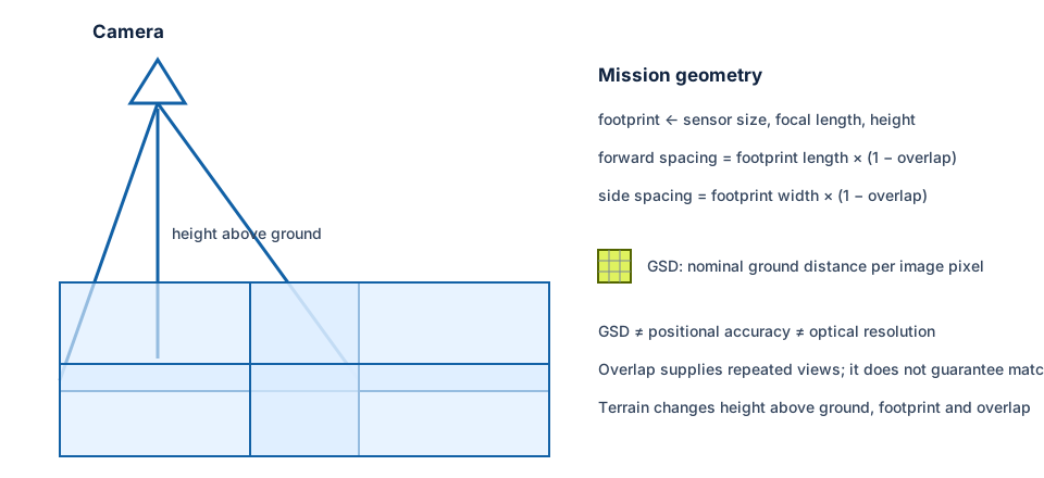
camera geometry → one ground footprint → overlapping footprints → matched views → reconstruction
Learner action
Create 02_mission_geometry.ipynb. Add one cell named Units first and convert every sensor dimension and focal length into the same unit before calculating anything.
2. Height changes several properties at once
For the same camera and near-nadir geometry, a higher height above ground usually produces:
- a larger image footprint;
- coarser nominal GSD;
- fewer images for a given area and overlap;
- broader coverage per exposure;
- potentially longer viewing distance and more atmospheric path, though usually modest at small-UAV heights.
A lower height usually produces a smaller footprint, finer GSD, more images, more triggering, more storage and more processing. It may also increase sensitivity to terrain, height-control error and motion relative to the smaller pixel footprint.
“Lower is better” is therefore not a scientific rule. If a plot response is defined at 5 m support, a 1 cm mosaic may add leaf shadows and movement without improving the inference. Very fine acquisition can increase operational and computational cost while producing redundant precision.
Height must be specified carefully. Height above take-off point, ellipsoidal altitude and height above local ground are not interchangeable. GSD and footprint depend primarily on camera-to-surface distance. Terrain variation changes that distance during a flight unless terrain-following or another height strategy is used.
3. Ground sampling distance from a simplified model
For a level surface, nadir view and simple pinhole-camera approximation:
sensor pixel size = sensor width / image width in pixels
GSD ≈ sensor pixel size × height above ground / focal length
Use consistent units. If sensor pixel size and focal length are both in millimetres, their ratio is unitless; multiplying by height in metres produces GSD in metres per pixel.
For the synthetic mission:
- sensor width = 13.2 mm;
- image width = 5,472 pixels;
- pixel size ≈ 0.002412 mm;
- height = 80 m;
- focal length = 8.8 mm;
- GSD ≈ 0.02193 m, or 2.19 cm per pixel.
This is nominal. The approximation does not represent relief, camera tilt, lens distortion, effective optical resolution, orthomosaic resampling or local reconstruction error.
Worked example — calculate GSD and footprint
Predict before running
If height decreases from 80 m to 60 m while the camera stays the same, will GSD and footprint become larger or smaller? By what factor?
sensor_width_mm = 13.2
sensor_height_mm = 8.8
image_width_px = 5472
focal_length_mm = 8.8
height_m = 80

pixel_size_mm = sensor_width_mm / image_width_px
gsd_m = pixel_size_mm * height_m / focal_length_mm
footprint_width_m = height_m * sensor_width_mm / focal_length_mm
footprint_height_m = height_m * sensor_height_mm / focal_length_mm

print("GSD (cm):", round(gsd_m * 100, 2))
print("footprint (m):", footprint_width_m, footprint_height_m)
Code walkthrough
- Sensor width and focal length use millimetres; height uses metres.
- Dividing width by pixel columns estimates physical pixel pitch.
- The pitch-to-focal-length ratio is multiplied by height.
- Multiplying by 100 converts metres to centimetres.
- Similar-triangle relationships estimate ground footprint width and height.
- The 80 m height produces an approximate 120 m × 80 m footprint.
- The result assumes the image axes align with cross-track and along-track directions.
- Terrain and camera orientation can change actual ground footprint.
Calculation check
Repeat for 60 m. You should obtain approximately 1.64 cm GSD and 90 m × 60 m footprint. All three linear quantities scale by 60/80 = 0.75 under this simplified geometry.
4. Forward and side overlap
Forward overlap is the shared area between consecutive images along a flight line. Side overlap is shared coverage between neighbouring flight lines. Both allow the same ground features to appear in multiple views.
If a footprint dimension along the flight direction is 80 m and forward overlap is 80%, approximate trigger spacing is:
80 m × (1 − 0.80) = 16 m
If cross-track footprint is 120 m and side overlap is 70%, approximate line spacing is:
120 m × (1 − 0.70) = 36 m
These are plan values. The achieved overlap varies with terrain height, platform attitude, wind, trigger timing, missing images and footprint orientation.
Overlap supports feature matching, multi-view geometry and redundancy. It does not guarantee sharp images, distinctive texture, good distribution of viewing directions, radiometric comparability or positional accuracy. One hundred blurred photographs of homogeneous water do not create reliable tie points.
5. Terrain changes height, GSD and overlap
A mission flown at constant altitude relative to take-off does not maintain constant height above ground. Over a hill, the camera is closer to the surface; GSD and footprint shrink. Over a depression, they grow. Planned overlap can fall below the expected value on high ground or become excessive elsewhere, depending on geometry.
Terrain-following can reduce variation when a suitable elevation model and compliant flight controller are available. It also introduces dependencies: the model’s resolution, date, surface meaning, vertical reference and errors become mission inputs. A DSM containing trees is not the same planning surface as bare terrain.
For flat coastal meadows, relief may be small, but reed beds, dunes, embankments and vegetation height still influence visible surface and occlusion. Tides change water boundaries, while textureless water contributes poor matches regardless of overlap.
Interpretation task
Sketch a profile with a 4 m embankment. Mark constant altitude above take-off and resulting camera-to-ground distances. Explain where nominal GSD and overlap depart from the plan.
6. Speed, trigger interval and blur
If along-track spacing is 16 m and groundspeed is 5 m/s, the approximate trigger interval is 3.2 seconds. That calculation assumes stable speed and no latency.
Motion during exposure can blur the image. At 5 m/s and 1/625 second exposure (0.0016 s), the platform moves about 8 mm during the exposure. The projected image effect depends on GSD, orientation, stabilisation and camera motion; the simple ground-distance comparison is only a warning metric.
Flight speed also interacts with:
- camera write time and triggering reliability;
- wind and actual groundspeed;
- turns and acceleration at line ends;
- exposure selected under changing light;
- rolling-shutter readout.
Review image_metadata.csv: IMG_0007 has a 1.8-pixel blur score and requires review. A complete plan defines a blur criterion and action rather than noticing the problem after mosaicking.
7. Global and rolling shutters
A global shutter exposes the image frame at effectively one time. A rolling shutter reads rows sequentially. During platform or scene motion, different rows can record slightly different camera poses, producing geometric distortion.
Rolling shutter is not automatically unusable. Flight speed, exposure, readout time, stabilisation and software modelling influence the result. The key professional action is to record shutter type and review whether motion-related deformation is modelled and independently validated.
A grass canopy also moves. Even with a global shutter, leaves can occupy different positions across overlapping images. Feature matching may reconstruct an averaged, noisy or duplicated surface.
8. Nadir, oblique and cross-grid geometry
A nadir mission points the camera approximately downward and is common for mapping. Oblique imagery adds side views that can improve three-dimensional geometry for vertical objects or complex surfaces but changes occlusion, footprint and radiometry.
A cross-grid or double-grid mission adds flight directions, increasing view diversity. It may help reconstruction in some contexts, but it increases images and mission time. It is not a universal quality switch. Vegetation movement, illumination change and operational exposure may also increase over a longer mission.
Design should reflect the target:
- planimetric meadow cover may prioritise consistent near-nadir observations;
- three-dimensional scrub structure may benefit from additional angles;
- thermal mapping may prioritise short acquisition time and stable conditions;
- low-texture surfaces may require carefully chosen geometry and independent evidence.
9. Mission coverage needs margins
The mapped study boundary is not the same as the flight boundary. Photogrammetric blocks are often weakest at edges because features have fewer viewing directions. A plan needs adequate margin outside the analysis area where lawful and safe.
Coverage QA should look for:
- missing lines or frames;
- gaps in intended multi-view coverage;
- weak edge geometry;
- turns contributing tilted or blurred frames;
- actual image centres and footprints;
- terrain-dependent overlap;
- obstacles and occluded zones.
Do not infer achieved coverage from the planned route alone. Use captured image positions, orientations and alignment results.
10. Common mistakes and recovery
GSD equals accuracy
Why: both are lengths. Detect: pixel size is the only evidence. Recover: report nominal GSD, effective detail and independent horizontal/vertical accuracy separately.
Higher overlap guarantees quality
Why: overlap is easy to specify. Detect: blur, water, moving canopy or poor block geometry are ignored. Recover: pair overlap with sharpness, texture, view diversity and achieved-coverage evidence.
Constant altitude means constant GSD
Why: flight altitude is a single number. Detect: terrain or surface variation is absent from planning. Recover: calculate camera-to-surface height and review terrain-following inputs.
Using planned overlap as achieved overlap
Why: mission software displays a percentage. Detect: no captured footprints or missing-frame audit exists. Recover: reconstruct achieved coverage from image metadata.
Selecting the finest possible GSD
Why: detail appears valuable. Detect: no target-support or cost rationale. Recover: choose resolution from the scientific unit, feature size, uncertainty, coverage and processing budget.
11. Guided practice — compare two meadow missions
Use the synthetic camera parameters and compare 80 m with 60 m height.
- Verify all units.
- Calculate pixel pitch, nominal GSD and footprint dimensions.
- Calculate forward and side spacing for 80%/70% overlap.
- At 5 m/s, calculate trigger intervals.
- Estimate relative image count for the same area using footprint spacing, not GSD alone.
- Add a 4 m terrain rise and recalculate local height, GSD and footprint.
- Record how storage, flight duration and reconstruction size change qualitatively.
- Mark assumptions: nadir, rectangular sensor, level reference surface and simple pinhole geometry.
- Choose a mission for a 5 m plot-mean vegetation question and defend the decision.
- Write one reason the alternative could be preferable under another question.
QGIS visual QA companion
Load study_area.geojson after transforming it to EPSG:3301. Create—not as an operational route, but as a teaching overlay—rectangles representing the calculated footprints and spacings. Check margins and edge coverage. Label them “nominal planned footprints.”
QA checklist
- Camera and height units are consistent.
- GSD equation and assumptions are explicit.
- Footprint axes and flight direction are declared.
- Forward and side spacing are calculated separately.
- Terrain and achieved coverage are reviewed.
- Speed, exposure, shutter and blur are connected.
- The design is justified by target support, not maximum detail.
12. Independent challenge — mission decision under constraints
A team must map 25 hectares within one short weather window. The ecological response is mean vegetation greenness for 10 m plots, not individual leaves. Compare:
- Mission A: approximately 1.6 cm GSD at 60 m;
- Mission B: approximately 2.7 cm GSD at 100 m.
For each, discuss footprint, approximate image count, overlap robustness over relief, blur risk, duration, storage, edge margins and target support. Recommend one, but include the evidence that could reverse your recommendation. Do not invoke jurisdiction-specific flight limits; state that current operational rules require separate verification.
Scientific interpretation
Mission geometry determines the opportunities for reconstruction and the nominal sampling lattice. It does not independently determine product accuracy or ecological validity. Good design balances repeated views, sharpness, stable illumination, area, terrain, time, target support and validation.
13. Reflection, submission and portfolio artifact
Answer in your private notes:
- How does height affect GSD and footprint?
- Why are forward and side overlap different?
- What does overlap support, and what does it not guarantee?
- How can terrain alter an apparently constant mission?
- When could finer GSD make an ecological workflow worse?
Submission
- Notebook:
02_mission_geometry.ipynbwith both designs and terrain sensitivity. - Table: mission design sheet with parameters, equations, assumptions and consequences.
- Diagram: nominal footprints and margins over the synthetic boundary.
- Written answer: 250–320 words defending one mission for the 10 m plot question.
Portfolio artifact
Artifact 2.19 — UAV mission-design sheet
Add the calculation workbook and decision note to the Professional UAV Product Audit and Processing Report. It becomes the acquisition-geometry contract used to judge the handover later.